
Custom Special-Shaped Stamping Punches — 5 CAD Drawing Guidelines to Accelerate Quoting & Prevent Chipping
Practical CAD drawing rules for ordering stepped, hex, oblong, and carbide punches — tolerance specifications, R-angle transitions, material grades, and surface roughness.
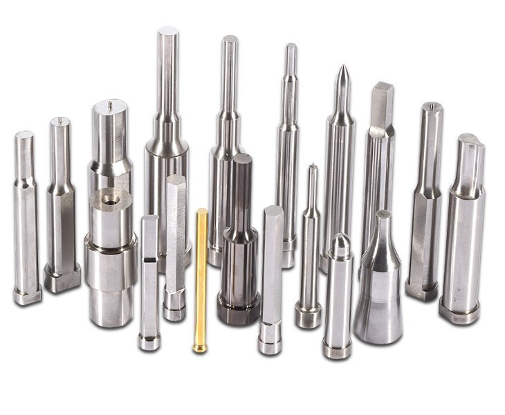
In precision sheet metal stamping and connector terminal manufacturing, non-standard and custom-shaped punches account for over 60% of tooling wear. When purchasing engineers or toolmakers submit RFQs (Request for Quotations), ambiguous drawings are the #1 reason for delayed quotes, extended sampling cycles, and premature punch fracture during production.
1. Clear Cross-Section & Complete Projection Views
Non-standard punches—such as hexagonal, oval, rectangular with corner radii, or multi-stepped configurations—often lack complete orthographic views.
- For regular polygonal shapes (e.g., Hexagon): Always specify the across-flats dimension (S dimension) as the primary inspection datum, rather than corner-to-corner across-points, to enable direct micrometer verification.
- For irregular profiles: Provide an orthogonal end-view with coordinate callouts or an auxiliary cross-section view. Supplying an accompanying STEP or IGES 3D CAD model eliminates 2D projection ambiguities.
2. Transition Radius (R) to Prevent Stress Concentration
Over 70% of premature punch fatigue fractures occur at the transition shoulder between the shank (D) and the working tip (d).
3. Stamping Punch Material Selection Matrix
Selecting the optimal tool steel balances impact toughness against abrasive wear resistance:
| Material Grade | Standard Hardness | Toughness vs Wear | Recommended Application |
|---|---|---|---|
| SKD11 / D2 / Cr12MoV | HRC 58–60 | Balanced / Standard | Mild steel, copper, aluminum blanking (under 2.0mm) |
| SKH-51 / M2 / 1.3343 | HRC 62–64 | High wear resistance | High-speed stamping, stainless steel 304, connector terminals |
| Tungsten Carbide (V30/CD650) | HRA 89–92 | Extreme wear resistance | Ultra-high-volume motor laminations, precision micro-stamping |
4. Realistic Tolerances and Datum References
While high-precision optical grinding can achieve tolerances of ±0.001 mm, applying tight tolerances globally across non-critical shank lengths increases production cost without adding functional value.
- Working Tip Contour: Typically ±0.002 mm to ±0.005 mm depending on blanking clearance requirements.
- Shank Diameter (Holding Fit): m5 or h6 for precision punch holder retention.
- Overall Length (OAL): ±0.02 mm to ensure uniform ground shut-height across multiple punch assemblies.
5. Surface Finish & PVD Coating Callouts
For high-cycle stamping lines, surface micro-roughness directly influences stripping friction and galling. Specify Ra 0.1–0.2 μm mirror polishing along the axial cutting direction on the working tip. Where abrasive wear or galling occurs (e.g., stamping stainless steel or galvanized sheet), recommend PVD coatings such as TiCN (Titanium Carbonitride) or AlCrN to multiply tool life by 300% to 500%.
CUSTOM DRAWING FABRICATION · FAST RFQ
Need a Precise Quote for Custom Mold Components?
YZX Precision specializes in tight-tolerance punches, ejector pins, and guide sets holding ±0.002mm. Upload your STEP, DWG, or PDF drawing for a rapid quotation within 2 business hours.
 Chat on WhatsApp